Programming a CNC wood router follows the same logical sequence every time: design, toolpath, verify, cut. The software handles the complex math. Your job is understanding what each step does and making the right decisions along the way. New operators who work through this systematically get good results quickly. Those who skip steps, particularly simulation and dry runs, find out why those steps exist the hard way.
What Is CNC Router Programming?
CNC router programming is the process of translating a design into machine instructions that tell the router where to move, how fast, and what tool to use. The end result is a G-code file the machine's controller reads and executes. Most operators never write G-code by hand: CAM software generates it automatically from toolpath settings applied to the design geometry. Understanding what the G-code represents, and being able to verify it before cutting, is what separates operators who run confidently from those who guess and hope.
How to Program a CNC Wood Router Step by Step
Create Your Design in CAD Software
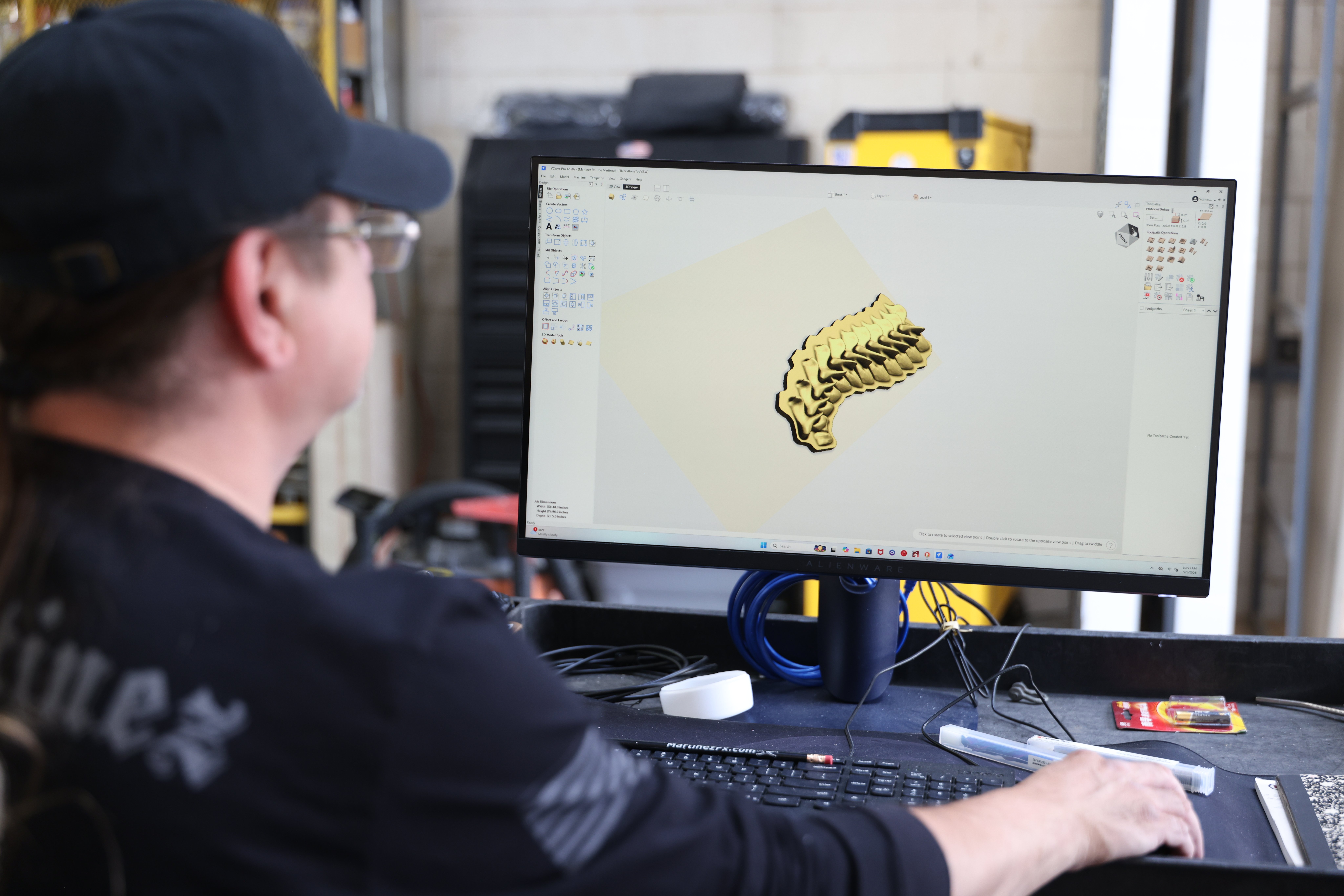
Start with a design file. For 2D work this is a vector drawing; for 3D carving, a 3D model. Dimensions need to be accurate and the geometry clean: overlapping lines, open vectors, and duplicate geometry all cause problems in CAM. Many operators import artwork from graphic design software and clean it up in their CAM tool before generating toolpaths.
Generate Toolpaths in CAM Software
CAM software translates design geometry into cutting tool movement paths. This is where you define the operation type for each piece of geometry: a profile cut, a pocket, an engraving pass, or a 3D contour. The CAM software also needs tool geometry and cut parameters before it can generate accurate toolpaths.
Select the Cutting Tool
Tool selection in CAM must match the physical tool loaded in the machine. Diameter, flute count, and cutting length all affect how toolpaths are calculated. Using the wrong tool definition generates toolpaths that do not match what the machine actually produces.
Set Speeds, Feeds, and Cutting Depth
Spindle speed, feed rate, and depth of cut need to match the material and tool. Too aggressive and you break tools or burn wood. Too conservative and you waste time or get poor surface quality. Test and document proven settings for each material and tool combination rather than relying on generic tables.
Generate and Check the G-Code
CAM generates G-code through a post-processor configured for your specific controller. Different controllers interpret G-code slightly differently, so using the correct post-processor matters. Review the output for obvious errors, unexpected rapid moves, or missing tool changes before moving to simulation.
Set the Work Coordinates and Offsets
Work coordinates tell the controller where the part origin is relative to the machine. When you zero the machine to a corner of the board, you are setting a work offset. Getting Z zero right, the height reference for depth of cut, is especially critical. Getting it wrong is one of the most common causes of damaged stock.
Simulate and Verify the Toolpaths
Simulation runs the program virtually before cutting anything. Good CAM software shows the tool moving through the material in 3D, letting you verify cut geometry and check for collisions with fixtures. Seconds in simulation versus hours in ruined stock if something is wrong.
Load the Program Into the CNC Router
Transfer the verified G-code to the machine controller via USB, network, or direct connection. Confirm the correct file is loaded and that the current tool matches what the program expects at its start point.
Perform a Dry Run
A dry run executes the program at full speed with the spindle off and the tool raised above the material. It verifies machine movement and work coordinates before any cutting happens. Run one on every new program and every new material setup.
Run and Monitor the First Cut
The first actual cut deserves full attention. Watch tool engagement, listen for unusual sounds, and be ready to hit feed hold if something looks wrong. Measure critical dimensions on the first part before running more. Problems caught on part one are easy to fix.
CNC Router Software You Will Need
CAD Software
Vectric VCarve and Aspire include built-in 2D and 3D design tools alongside CAM. Fusion 360 provides full parametric 3D CAD integrated with CAM. Adobe Illustrator and CorelDRAW are commonly used for 2D artwork imported into CAM for toolpath generation.
CAM Software
Vectric VCarve Pro and Aspire are the most widely used in wood routing for their accessible interface and strong toolpath quality across 2D and 3D work. Fusion 360 CAM suits operators needing more advanced strategies. Carveco is a capable option for carving-focused work.
CNC Control Software
Control software runs on the machine's computer and interprets G-code to drive the motors. Mach4, UCCNC, and manufacturer-supplied controllers are common in professional machines. The control software manages real-time machine communication, work coordinates, and feed rate overrides.
G-Code Sender and Editing Software
G-code sender software like Universal G-code Sender (UGS) handles file transfer for simpler setups. Most production operators rarely edit G-code directly, but being able to read it well enough to spot obvious errors is a useful skill.
Simulation Software
Most professional CAM software includes built-in simulation. Standalone tools like CAMotics allow G-code verification independent of the CAM package. Treat simulation as non-negotiable on any new program.

CNC Programming Terms Beginners Should Know
G-Code
G-code is the programming language CNC machines use. G0 is a rapid move, G1 is a feed move, G2 and G3 are arc moves. CAM generates it automatically, but understanding the basic commands helps operators verify output and diagnose unexpected behavior.
Toolpaths
A toolpath is the programmed path the cutting tool follows. Profile toolpaths cut along geometry edges. Pocket toolpaths remove material inside a boundary. Contour toolpaths follow 3D surface geometry. Choosing the right toolpath type for each operation is a core CAM decision.
Work Coordinates and Offsets
Work coordinates define where the part origin is relative to the machine's home position. Operators set X, Y, and Z zero on the material before each job. Getting Z zero right is critical for cut depth accuracy and avoiding tool or material damage.
Speeds and Feeds
Spindle RPM and feed rate together determine chip load, the amount of material each cutting edge removes per revolution. Chip load drives cut quality, tool life, and heat generation. Start from published recommendations and refine based on actual results.
Tool Radius Compensation
Tool radius compensation adjusts the toolpath to account for the physical radius of the cutting tool so finished dimensions match the design. Most CAM software handles this automatically, but understanding it helps when parts come out the wrong size.
How to Choose CNC Router Programming Software
Free vs. Paid CNC Software
Free options work for basic applications. Paid software like VCarve Pro and Aspire provides better toolpath quality, more operation types, better simulation, and stronger post-processor support. For production work, the cost is minor compared to the machine investment.
Beginner-Friendly Software
Vectric VCarve is widely recommended for new operators because it combines accessible design tools with capable CAM, and the training resources are extensive. Easel and Carbide Create suit simpler 2D work on entry-level machines.
Advanced CNC Programming Features
Production shops benefit from nesting software for sheet utilization, automatic tool change management, and more sophisticated toolpath strategies. Fusion 360 and Aspire both support advanced toolpaths that basic software cannot generate.
Common CNC Router Programming Mistakes
Incorrect Speeds and Feeds
Wrong parameters cause poor cut quality, burned wood, and broken bits. Test and document proven settings for each material and tool combination rather than copying from a generic table without verification.
Wrong Tool or Toolpath Settings
Wrong tool diameter in CAM, the wrong toolpath type, or insufficient step-down depth all produce results that do not match the design. Review toolpath settings carefully before generating G-code.
Incorrect Work Coordinates
Setting X, Y, or Z zero in the wrong location causes cuts that start in the wrong place or go too deep. Verify work coordinates before every job. A dry run exposes most coordinate errors before they damage stock.
Skipping Simulation or a Dry Run
Simulation verifies the toolpath in software. The dry run verifies machine movement in the real world. Skipping either one is rarely worth the risk, particularly on a new program or new setup.
CNC Router Programming Safety Tips
Keep the area around the machine clear while it is running. Never reach into the cutting zone while the spindle is moving. Use feed hold rather than emergency stop for non-emergency pauses. Wear eye protection whenever the machine is running. Know where the emergency stop is before the first cut. Secure the workpiece properly before starting any job: a part that lifts during a cut becomes a projectile.
How to Learn CNC Router Programming
The fastest path to competence is running jobs on real material. Vectric's training resources are extensive and well-organized for operators using their software. YouTube has a large library of practical CNC programming tutorials. CNC forums organized around specific machines are useful for troubleshooting specific problems. The process becomes clear when you work through the full sequence from design to finished cut and see how each step affects the output. Start running parts as early as possible.